Extacting Regions of Interest using Page Markers

Categories Computer Vision, Uncategorized

Source on GitHub: https://github.com/ayoungprogrammer/OMR-Example

Introduction

Optical Mark Recognition is recognizing certain “marks” on an image and using those marks as a reference point to extract other regions of interest (ROI) on the page. OMR is a relatively new technology and there is close to no documentation on the subject. Current OMR technologies like ScanTron require custom machines designed specifically to scan custom sheets of paper. These methods work well but the cost to produce the machines and paper is high as well as the inflexibility. Hopefully I can provide some insight into creating an efficient and effective OMR algorithm that uses standard household scanners and a simple template.

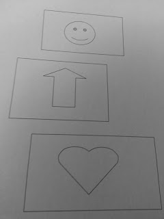
An OMR algorithm first needs a template page to know where ROI’s are in relation to the markers. It then needs to be able to scan a page and recognize where the markers are. Then using the template, the algorithm can determine where the ROI’s are in relation to the markers. In the case of ScanTrons, the markers are the black lines on the sides and ROI’s are the bubbles that are checked.

For an effective OMR, the markers should be at least halfway across the page from each other (either vertically or horizontally). The further apart the markers are, the higher accuracy you will achieve.

For the simplicity of this tutorial, we will use two QR codes with one in each corner as the markers. This will be our template:

Opening the template in Paint, we can find the coordinate of the ROI’s and markers.
Markers:
Top right point of first QR code:
1084,76
Bottom left point of second QR code:
77,1436
Region of Interests (ROI’s)
Name box:
(223,105) -> (603,152)
Payroll # box:
(223,152)->(603, 198)
Sin box:
(223, 198)->(603,244)
Address box:
(223,244)->(603,290)
Postal box:
(223, 291)->(603,336)
Picture:
(129,491) -> (766,806)

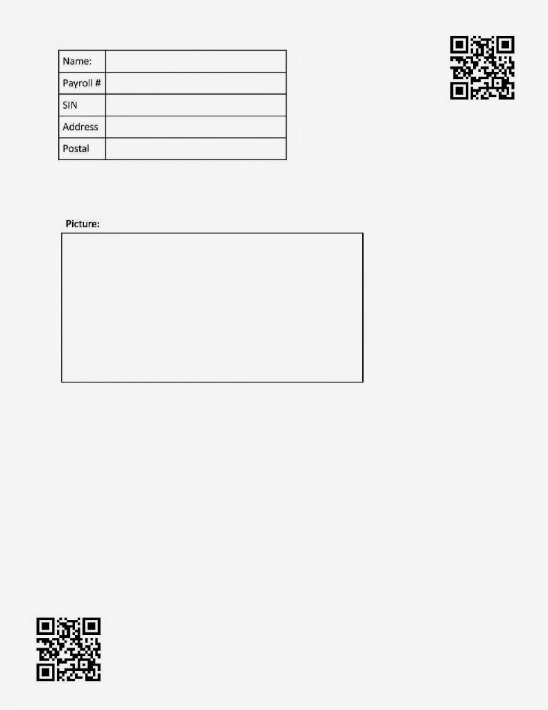
Using the coordinate we can do some simple math to find the relative positioning of the ROI’s.

We can also find the angle of rotation from the markers. If we find the angle between the top right corner and bottom left corner of the template markers we get: 53.48222 degrees. If we find that the markers we scan have is something different from that angle, we rotate the whole page by that angle, it will fix the skewed rotation.
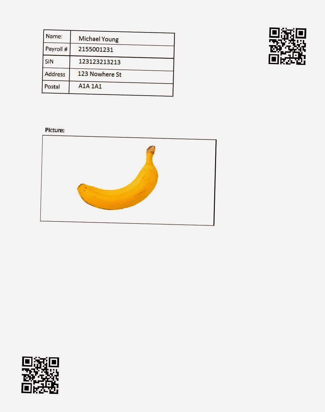
Scanned image:

OMR Processed Image + Fixed rotation

Extensions

Two QR Codes in each corner looks ugly but there are many other types of markers you can use.
Once you have the coordinates of the ROI’s you can easily extract them and possibly OCR the data you need.
If you want to OMR a page where you have no control over the template you need to do some heuristics to find some sort of markers on the page (for example looking for a logo or line detection).
You can easily add an extension for multiple choice or checkboxes and extract the ROI to determine the selection.
In real applications you will want to create your own template dynamically and encode the ROI data somewhere so you do not have to manually enter the coordinates of the marker and ROI’s.

Source Code

Source on Github: https://github.com/ayoungprogrammer/OMR-Example


#include <opencv2/highgui/highgui.hpp>
#include <opencv2/imgproc/imgproc.hpp>
#include <zbar.h>
#include <iostream>

using namespace cv;
using namespace std;
using namespace zbar;

//g++ main.cpp /usr/local/include/ /usr/local/lib/ -lopencv_highgui.2.4.8 -lopencv_core.2.4.8

void drawQRCodes(Mat img,Image& image){
  // extract results 
  for(Image::SymbolIterator symbol=image.symbol_begin(); symbol != image.symbol_end();++symbol) { 
    vector<Point> vp; 

    //draw QR Codes
    int n = symbol->get_location_size(); 
    for(int i=0;i<n;i++){ 
      vp.push_back(Point(symbol->get_location_x(i),symbol->get_location_y(i))); 
    } 
    RotatedRect r = minAreaRect(vp); 
    Point2f pts[4]; 
    r.points(pts); 
    //Display QR code
    for(int i=0;i<4;i++){ 
      line(img,pts[i],pts[(i+1)%4],Scalar(255,0,0),3); 
    } 
  } 
}

Rect makeRect(float x,float y,float x2,float y2){
  return Rect(Point2f(x,y),Point2f(x2,y2));
}

Point2f rotPoint(Point2f p,Point2f o,double rad){
  Point2f p1 = Point2f(p.x-o.x,p.y-o.y);

  return Point2f(p1.x * cos(rad)-p1.y*sin(rad)+o.x,p1.x*sin(rad)+p1.y*cos(rad)+o.y);
}

void drawRects(Mat& img,Point2f rtr,Point2f rbl){
  vector<Rect> rects;

  Point2f tr(1084,76);
  Point2f bl(77,1436);

  rects.push_back(makeRect(223,105,603,152));
  rects.push_back(makeRect(223,152,603,198));
  rects.push_back(makeRect(223,198,603,244));
  rects.push_back(makeRect(223,244,603,290));
  rects.push_back(makeRect(223,291,603,336));

  rects.push_back(makeRect(129,491,765,806));


  //Fix rotation angle
  double angle = atan2(tr.y-bl.y,tr.x-bl.x);
  double realAngle = atan2(rtr.y-rbl.y,rtr.x-rbl.x);

  double angleShift = -(angle-realAngle);

  //Rotate image
  Point2f rc((rtr.x+rbl.x)/2,(rbl.y+rtr.y)/2);
  Mat rotMat = getRotationMatrix2D(rc,angleShift/3.14159265359*180.0,1.0);
  warpAffine(img,img,rotMat,Size(img.cols,img.rows),INTER_CUBIC,BORDER_TRANSPARENT);

  rtr = rotPoint(rtr,rc,-angleShift);
  rbl = rotPoint(rbl,rc,-angleShift);

  //Calculate ratio between template and real image
  double realWidth = rtr.x-rbl.x;
  double realHeight = rbl.y-rtr.y;

  double width = tr.x-bl.x;
  double height = bl.y - tr.y;

  double wr = realWidth/width;
  double hr = realHeight/height;

  circle(img,rbl,3,Scalar(0,255,0),2);
  circle(img,rtr,3,Scalar(0,255,0),2);

  for(int i=0;i<rects.size();i++){
    Rect r = rects[i];
    double x1 = (r.x-tr.x)*wr+rtr.x;
    double y1 = (r.y-tr.y)*hr+rtr.y;
    double x2 = (r.x+r.width-tr.x)*wr +rtr.x;
    double y2 = (r.y+r.height-tr.y)*hr + rtr.y;
    rectangle(img,Point2f(x1,y1),Point2f(x2,y2),Scalar(0,0,255),3);
    //circle(img,Point2f(x1,y1),3,Scalar(0,0,255));
  }
}

int main(int argc, char* argv[])
{
  Mat img = imread(argv[1]);

  ImageScanner scanner; 
  scanner.set_config(ZBAR_NONE, ZBAR_CFG_ENABLE, 1); 

  namedWindow("OMR",CV_WINDOW_AUTOSIZE); //create a window

  Mat grey;
  cvtColor(img,grey,CV_BGR2GRAY);

  int width = img.cols; 
  int height = img.rows; 
  uchar *raw = (uchar *)grey.data; 
  // wrap image data 
  Image image(width, height, "Y800", raw, width * height); 
  // scan the image for barcodes 
  scanner.scan(image); 

  //Top right point
  Point2f tr(0,0);
  Point2f bl(0,0);

  // extract results 
  for(Image::SymbolIterator symbol = image.symbol_begin(); symbol != image.symbol_end();++symbol) { 
    vector<Point> vp; 

   //Find TR point
   if(tr.y==0||tr.y>symbol->get_location_y(3)){
     tr = Point(symbol->get_location_x(3),symbol->get_location_y(3));
   }

   //Find BL point
   if(bl.y==0||bl.y<symbol->get_location_y(1)){
     bl = Point(symbol->get_location_x(1),symbol->get_location_y(1));
   }
  } 

  drawQRCodes(img,image);
  drawRects(img,tr,bl);
  imwrite("omr.jpg", img); 

  return 0;
}

Tutorial: Detection / recognition of multiple rectangles and extracting with OpenCV

Categories Computer Vision, Uncategorized

 This tutorial will be focused on being able to take a picture and extract the rectangles in the image that are above a certain size:

I am using OpenCV 2.4.2 on Microsoft Visual Express 2008 but it should work with other version as well.

Thanks to: opencv-code.com for their helpful guides

Step 1: Clean up

So once again, we’ll use my favourite snippet for cleaning up an image:
Apply a Gaussian blur and using an adaptive threshold for binarzing the image
//Apply blur to smooth edges and use adapative thresholding  
 cv::Size size(3,3);  
 cv::GaussianBlur(img,img,size,0);  
 adaptiveThreshold(img, img,255,CV_ADAPTIVE_THRESH_MEAN_C, CV_THRESH_BINARY,75,10);  
 cv::bitwise_not(img, img);  

Step 2: Hough Line detection

Use a probabilistic Hough line detection to figure out where the lines are. This algorithm works by going through every point in the image and checking every angle. 
 vector<Vec4i> lines;  
 HoughLinesP(img, lines, 1, CV_PI/180, 80, 100, 10);  
And here we have the results of the algorithm:

Step 3: Use connected components to determine what they shapes are

This is the most complex part of the algorithm (general pseudocode):
First, initialize every line to be in an undefined group
For every line compute the intersection of the two line segments (if they do not intersect ignore the point)
      If both lines are undefined, make a new group out of them
      If only one line is defined in a group, add the other line into the group. 
      If both lines are defined than add all the lines from one group into the other group
      If both lines are in the same group, do nothing
cv::Point2f computeIntersect(cv::Vec4i a, cv::Vec4i b)  
 {  
   int x1 = a[0], y1 = a[1], x2 = a[2], y2 = a[3];  
   int x3 = b[0], y3 = b[1], x4 = b[2], y4 = b[3];  
   if (float d = ((float)(x1-x2) * (y3-y4)) - ((y1-y2) * (x3-x4)))  
   {  
     cv::Point2f pt;  
     pt.x = ((x1*y2 - y1*x2) * (x3-x4) - (x1-x2) * (x3*y4 - y3*x4)) / d;  
     pt.y = ((x1*y2 - y1*x2) * (y3-y4) - (y1-y2) * (x3*y4 - y3*x4)) / d;  
           //-10 is a threshold, the POI can be off by at most 10 pixels
           if(pt.x<min(x1,x2)-10||pt.x>max(x1,x2)+10||pt.y<min(y1,y2)-10||pt.y>max(y1,y2)+10){  
                return Point2f(-1,-1);  
           }  
           if(pt.x<min(x3,x4)-10||pt.x>max(x3,x4)+10||pt.y<min(y3,y4)-10||pt.y>max(y3,y4)+10){  
                return Point2f(-1,-1);  
           }  
     return pt;  
   }  
   else  
     return cv::Point2f(-1, -1);  
 }  
Connected components
int* poly = new int[lines.size()];  
  for(int i=0;i<lines.size();i++)poly[i] = - 1;  
  int curPoly = 0;  
       vector<vector<cv::Point2f> > corners;  
      for (int i = 0; i < lines.size(); i++)  
      {  
           for (int j = i+1; j < lines.size(); j++)  
           {  
          
                cv::Point2f pt = computeIntersect(lines[i], lines[j]);  
                if (pt.x >= 0 && pt.y >= 0&&pt.x<img2.size().width&&pt.y<img2.size().height){  
              
                     if(poly[i]==-1&&poly[j] == -1){  
                          vector<Point2f> v;  
                          v.push_back(pt);  
                          corners.push_back(v);       
                          poly[i] = curPoly;  
                          poly[j] = curPoly;  
                          curPoly++;  
                          continue;  
                     }  
                     if(poly[i]==-1&&poly[j]>=0){  
                          corners[poly[j]].push_back(pt);  
                          poly[i] = poly[j];  
                          continue;  
                     }  
                     if(poly[i]>=0&&poly[j]==-1){  
                          corners[poly[i]].push_back(pt);  
                          poly[j] = poly[i];  
                          continue;  
                     }  
                     if(poly[i]>=0&&poly[j]>=0){  
                          if(poly[i]==poly[j]){  
                               corners[poly[i]].push_back(pt);  
                               continue;  
                          }  
                        
                          for(int k=0;k<corners[poly[j]].size();k++){  
                               corners[poly[i]].push_back(corners[poly[j]][k]);  
                          }  
                       
                          corners[poly[j]].clear();  
                          poly[j] = poly[i];  
                          continue;  
                     }  
                }  
           }  
      }  
The circles represent the points of intersection and the colours represent the different shapes. 

Step 4: Find corners of the polygon

Now we need to find corners of the polygons to get the polygon formed from the point of intersections.
Pseudocode:
For each group of points:
       Compute mass center (average of points)
        For each point that is above the mass center, add to top list
        For each point that is below the mass center, add to bottom list
        Sort top list and bottom list by x val
       first element of top list is  left most (top left point)
        last element of top list is right most (top right point) 
       first element of bottom list is  left most  (bottom left point)
       last element of bottom list is right most  (bottom right point) 


 bool comparator(Point2f a,Point2f b){  
           return a.x<b.x;  
      }  
 void sortCorners(std::vector<cv::Point2f>& corners, cv::Point2f center)  
 {  
   std::vector<cv::Point2f> top, bot;  
   for (int i = 0; i < corners.size(); i++)  
   {  
     if (corners[i].y < center.y)  
       top.push_back(corners[i]);  
     else  
       bot.push_back(corners[i]);  
   }  
      sort(top.begin(),top.end(),comparator);  
      sort(bot.begin(),bot.end(),comparator);  
   cv::Point2f tl = top[0];
   cv::Point2f tr = top[top.size()-1];
   cv::Point2f bl = bot[0];
   cv::Point2f br = bot[bot.size()-1];  
   corners.clear();  
   corners.push_back(tl);  
   corners.push_back(tr);  
   corners.push_back(br);  
   corners.push_back(bl);  
 }  
for(int i=0;i<corners.size();i++){  
           cv::Point2f center(0,0);  
           if(corners[i].size()<4)continue;  
           for(int j=0;j<corners[i].size();j++){  
                center += corners[i][j];  
           }  
           center *= (1. / corners[i].size());  
           sortCorners(corners[i], center);  
      }  

Step 5: Extraction

The final step is extract each rectangle from the image. We can do this quite easily with the perspective transform from OpenCV. To get an estimate of the dimensions of the rectangle we can use a bounding rectangle of the corners. If the dimensions of that rectangle are under our wanted area, we ignore the polygon. If the polygon also has less than 4 points we can ignore it as well. 
for(int i=0;i<corners.size();i++){  
           if(corners[i].size()<4)continue;  
           Rect r = boundingRect(corners[i]);  
           if(r.area()<50000)continue;  
           cout<<r.area()<<endl;  
           // Define the destination image  
           cv::Mat quad = cv::Mat::zeros(r.height, r.width, CV_8UC3);  
           // Corners of the destination image  
           std::vector<cv::Point2f> quad_pts;  
           quad_pts.push_back(cv::Point2f(0, 0));  
           quad_pts.push_back(cv::Point2f(quad.cols, 0));  
           quad_pts.push_back(cv::Point2f(quad.cols, quad.rows));  
           quad_pts.push_back(cv::Point2f(0, quad.rows));  
           // Get transformation matrix  
           cv::Mat transmtx = cv::getPerspectiveTransform(corners[i], quad_pts);  
           // Apply perspective transformation  
           cv::warpPerspective(img3, quad, transmtx, quad.size());  
           stringstream ss;  
           ss<<i<<".jpg";  
           imshow(ss.str(), quad);  
      }