Real time QR Code / Bar code detection with webcam using OpenCV and ZBar

Categories Computer Vision, Uncategorized

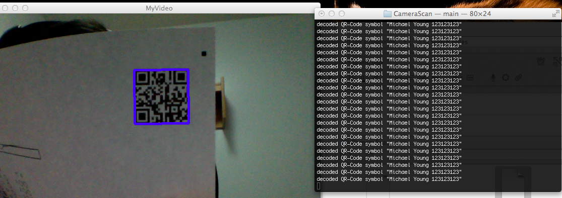
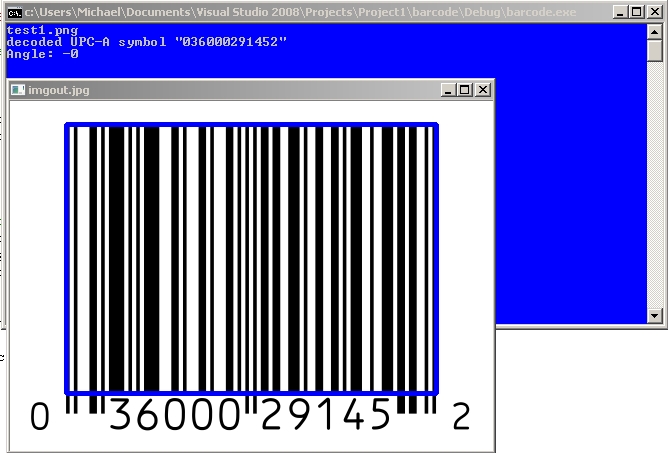
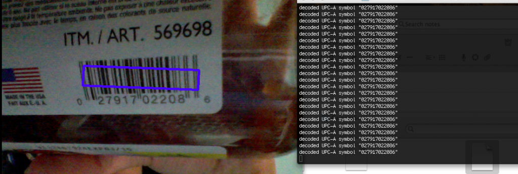
Tutorial: Real time QR Code / Bar code detection using webcam video feed / stream using OpenCV and ZBar

Pre-requisites:

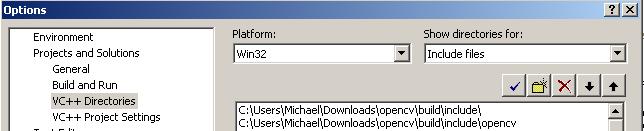
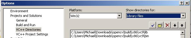
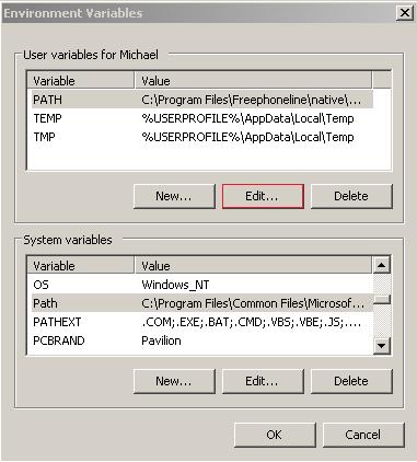
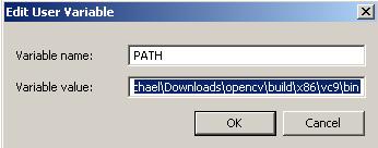
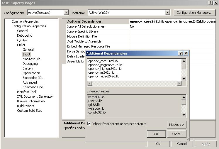
You will need to have installed OpenCV and ZBar (see previous tutorials) for this to work.

Source on Github:  https://github.com/ayoungprogrammer/WebcamCodeScanner

Code:

 #include <opencv2/highgui/highgui.hpp>  
 #include <opencv2/imgproc/imgproc.hpp>  
 #include <zbar.h>  
 #include <iostream>  
 using namespace cv;  
 using namespace std;  
 using namespace zbar;  
 //g++ main.cpp /usr/local/include/ /usr/local/lib/ -lopencv_highgui.2.4.8 -lopencv_core.2.4.8  
 int main(int argc, char* argv[])  
 {  
   VideoCapture cap(0); // open the video camera no. 0  
   // cap.set(CV_CAP_PROP_FRAME_WIDTH,800);  
   // cap.set(CV_CAP_PROP_FRAME_HEIGHT,640);  
   if (!cap.isOpened()) // if not success, exit program  
   {  
     cout << "Cannot open the video cam" << endl;  
     return -1;  
   }  
   ImageScanner scanner;   
    scanner.set_config(ZBAR_NONE, ZBAR_CFG_ENABLE, 1);   
   double dWidth = cap.get(CV_CAP_PROP_FRAME_WIDTH); //get the width of frames of the video  
   double dHeight = cap.get(CV_CAP_PROP_FRAME_HEIGHT); //get the height of frames of the video  
   cout << "Frame size : " << dWidth << " x " << dHeight << endl;  
   namedWindow("MyVideo",CV_WINDOW_AUTOSIZE); //create a window called "MyVideo"  
   while (1)  
   {  
     Mat frame;  
     bool bSuccess = cap.read(frame); // read a new frame from video  
      if (!bSuccess) //if not success, break loop  
     {  
        cout << "Cannot read a frame from video stream" << endl;  
        break;  
     }  
     Mat grey;  
     cvtColor(frame,grey,CV_BGR2GRAY);  
     int width = frame.cols;   
     int height = frame.rows;   
     uchar *raw = (uchar *)grey.data;   
     // wrap image data   
     Image image(width, height, "Y800", raw, width * height);   
     // scan the image for barcodes   
     int n = scanner.scan(image);   
     // extract results   
     for(Image::SymbolIterator symbol = image.symbol_begin();   
     symbol != image.symbol_end();   
     ++symbol) {   
         vector<Point> vp;   
     // do something useful with results   
     cout << "decoded " << symbol->get_type_name() << " symbol "" << symbol->get_data() << '"' <<" "<< endl;   
       int n = symbol->get_location_size();   
       for(int i=0;i<n;i++){   
         vp.push_back(Point(symbol->get_location_x(i),symbol->get_location_y(i)));   
       }   
       RotatedRect r = minAreaRect(vp);   
       Point2f pts[4];   
       r.points(pts);   
       for(int i=0;i<4;i++){   
         line(frame,pts[i],pts[(i+1)%4],Scalar(255,0,0),3);   
       }   
       //cout<<"Angle: "<<r.angle<<endl;   
     }   
     imshow("MyVideo", frame); //show the frame in "MyVideo" window  
     if (waitKey(30) == 27) //wait for 'esc' key press for 30ms. If 'esc' key is pressed, break loop  
     {  
       cout << "esc key is pressed by user" << endl;  
       break;   
     }  
   }  
   return 0;  
 }  

To Test

Find any QR code or bar code and hold it close to your webcam and it should pick up.

Tutorial: Scanning Barcodes / QR Codes with OpenCV using ZBar

Categories Computer Vision, Uncategorized
With the ZBar library, scanning Barcodes / QR codes is quite simple. ZBar is able to identify multiple bar code /qr code types and able to give the coords of their locations.

This tutorial was written using:
Microsoft Visual Studio 2008 Express
OpenCV 2.4.2
Windows Vista 32-bit
ZBar 0.1

You will need OpenCV installed before doing this tutorial

Tutorial here: http://ayoungprogrammer.blogspot.ca/2012/10/tutorial-install-opencv-242-for-windows.html

1. Install ZBar (Windows Installer)

http://sourceforge.net/projects/zbar/files/zbar/0.10/zbar-0.10-setup.exe/download

Check install developmental libraries and headers (You will need this)

Install ZBar in the default directory
“C:Program FilesZBar”

2. Import headers and libraries

Tools ->Options 

Projects & Solutions -> VC++ Directories
Go to “Include files” and add: “C:Program FilesZBarinclude”

 Go to “Library files and add: “C:Program FilesZBarlib”

3. Link libraries in current project

Create an empy blank console project
Right click your project -> Properties -> Configuration Properties -> Linker -> Input

In additional dependencies copy and paste the following:
libzbar-0.lib
opencv_core242d.lib
opencv_imgproc242d.lib
opencv_highgui242d.lib
opencv_ml242d.lib
opencv_video242d.lib
opencv_features2d242d.lib
opencv_calib3d242d.lib
opencv_objdetect242d.lib
opencv_contrib242d.lib
opencv_legacy242d.lib
opencv_flann242d.lib

4. Test Program

Make a new file in your project: main.cpp
 #include "zbar.h"  
 #include "cv.h"  
 #include "highgui.h"  
 #include <iostream>  
 using namespace std;  
 using namespace zbar;  
 using namespace cv;  
 int main(void){  
      ImageScanner scanner;  
      scanner.set_config(ZBAR_NONE, ZBAR_CFG_ENABLE, 1);  
       // obtain image data  
      char file[256];  
      cin>>file;  
      Mat img = imread(file,0);  
      Mat imgout;  
      cvtColor(img,imgout,CV_GRAY2RGB);  
      int width = img.cols;  
      int height = img.rows;  
   uchar *raw = (uchar *)img.data;  
   // wrap image data  
   Image image(width, height, "Y800", raw, width * height);  
   // scan the image for barcodes  
   int n = scanner.scan(image);  
   // extract results  
   for(Image::SymbolIterator symbol = image.symbol_begin();  
     symbol != image.symbol_end();  
     ++symbol) {  
                vector<Point> vp;  
     // do something useful with results  
     cout << "decoded " << symbol->get_type_name()  
        << " symbol "" << symbol->get_data() << '"' <<" "<< endl;  
           int n = symbol->get_location_size();  
           for(int i=0;i<n;i++){  
                vp.push_back(Point(symbol->get_location_x(i),symbol->get_location_y(i))); 
           }  
           RotatedRect r = minAreaRect(vp);  
           Point2f pts[4];  
           r.points(pts);  
           for(int i=0;i<4;i++){  
                line(imgout,pts[i],pts[(i+1)%4],Scalar(255,0,0),3);  
           }  
           cout<<"Angle: "<<r.angle<<endl;  
   }  
      imshow("imgout.jpg",imgout);  
   // clean up  
   image.set_data(NULL, 0);  
       waitKey();  
 }  

5. Copy libzbar-0.dll from C:/Program Files/ZBar/bin to your project folder

6. Run program 

Sample Images

Tutorial: Detection / recognition of multiple rectangles and extracting with OpenCV

Categories Computer Vision, Uncategorized

 This tutorial will be focused on being able to take a picture and extract the rectangles in the image that are above a certain size:

I am using OpenCV 2.4.2 on Microsoft Visual Express 2008 but it should work with other version as well.

Thanks to: opencv-code.com for their helpful guides

Step 1: Clean up

So once again, we’ll use my favourite snippet for cleaning up an image:
Apply a Gaussian blur and using an adaptive threshold for binarzing the image
//Apply blur to smooth edges and use adapative thresholding  
 cv::Size size(3,3);  
 cv::GaussianBlur(img,img,size,0);  
 adaptiveThreshold(img, img,255,CV_ADAPTIVE_THRESH_MEAN_C, CV_THRESH_BINARY,75,10);  
 cv::bitwise_not(img, img);  

Step 2: Hough Line detection

Use a probabilistic Hough line detection to figure out where the lines are. This algorithm works by going through every point in the image and checking every angle. 
 vector<Vec4i> lines;  
 HoughLinesP(img, lines, 1, CV_PI/180, 80, 100, 10);  
And here we have the results of the algorithm:

Step 3: Use connected components to determine what they shapes are

This is the most complex part of the algorithm (general pseudocode):
First, initialize every line to be in an undefined group
For every line compute the intersection of the two line segments (if they do not intersect ignore the point)
      If both lines are undefined, make a new group out of them
      If only one line is defined in a group, add the other line into the group. 
      If both lines are defined than add all the lines from one group into the other group
      If both lines are in the same group, do nothing
cv::Point2f computeIntersect(cv::Vec4i a, cv::Vec4i b)  
 {  
   int x1 = a[0], y1 = a[1], x2 = a[2], y2 = a[3];  
   int x3 = b[0], y3 = b[1], x4 = b[2], y4 = b[3];  
   if (float d = ((float)(x1-x2) * (y3-y4)) - ((y1-y2) * (x3-x4)))  
   {  
     cv::Point2f pt;  
     pt.x = ((x1*y2 - y1*x2) * (x3-x4) - (x1-x2) * (x3*y4 - y3*x4)) / d;  
     pt.y = ((x1*y2 - y1*x2) * (y3-y4) - (y1-y2) * (x3*y4 - y3*x4)) / d;  
           //-10 is a threshold, the POI can be off by at most 10 pixels
           if(pt.x<min(x1,x2)-10||pt.x>max(x1,x2)+10||pt.y<min(y1,y2)-10||pt.y>max(y1,y2)+10){  
                return Point2f(-1,-1);  
           }  
           if(pt.x<min(x3,x4)-10||pt.x>max(x3,x4)+10||pt.y<min(y3,y4)-10||pt.y>max(y3,y4)+10){  
                return Point2f(-1,-1);  
           }  
     return pt;  
   }  
   else  
     return cv::Point2f(-1, -1);  
 }  
Connected components
int* poly = new int[lines.size()];  
  for(int i=0;i<lines.size();i++)poly[i] = - 1;  
  int curPoly = 0;  
       vector<vector<cv::Point2f> > corners;  
      for (int i = 0; i < lines.size(); i++)  
      {  
           for (int j = i+1; j < lines.size(); j++)  
           {  
          
                cv::Point2f pt = computeIntersect(lines[i], lines[j]);  
                if (pt.x >= 0 && pt.y >= 0&&pt.x<img2.size().width&&pt.y<img2.size().height){  
              
                     if(poly[i]==-1&&poly[j] == -1){  
                          vector<Point2f> v;  
                          v.push_back(pt);  
                          corners.push_back(v);       
                          poly[i] = curPoly;  
                          poly[j] = curPoly;  
                          curPoly++;  
                          continue;  
                     }  
                     if(poly[i]==-1&&poly[j]>=0){  
                          corners[poly[j]].push_back(pt);  
                          poly[i] = poly[j];  
                          continue;  
                     }  
                     if(poly[i]>=0&&poly[j]==-1){  
                          corners[poly[i]].push_back(pt);  
                          poly[j] = poly[i];  
                          continue;  
                     }  
                     if(poly[i]>=0&&poly[j]>=0){  
                          if(poly[i]==poly[j]){  
                               corners[poly[i]].push_back(pt);  
                               continue;  
                          }  
                        
                          for(int k=0;k<corners[poly[j]].size();k++){  
                               corners[poly[i]].push_back(corners[poly[j]][k]);  
                          }  
                       
                          corners[poly[j]].clear();  
                          poly[j] = poly[i];  
                          continue;  
                     }  
                }  
           }  
      }  
The circles represent the points of intersection and the colours represent the different shapes. 

Step 4: Find corners of the polygon

Now we need to find corners of the polygons to get the polygon formed from the point of intersections.
Pseudocode:
For each group of points:
       Compute mass center (average of points)
        For each point that is above the mass center, add to top list
        For each point that is below the mass center, add to bottom list
        Sort top list and bottom list by x val
       first element of top list is  left most (top left point)
        last element of top list is right most (top right point) 
       first element of bottom list is  left most  (bottom left point)
       last element of bottom list is right most  (bottom right point) 


 bool comparator(Point2f a,Point2f b){  
           return a.x<b.x;  
      }  
 void sortCorners(std::vector<cv::Point2f>& corners, cv::Point2f center)  
 {  
   std::vector<cv::Point2f> top, bot;  
   for (int i = 0; i < corners.size(); i++)  
   {  
     if (corners[i].y < center.y)  
       top.push_back(corners[i]);  
     else  
       bot.push_back(corners[i]);  
   }  
      sort(top.begin(),top.end(),comparator);  
      sort(bot.begin(),bot.end(),comparator);  
   cv::Point2f tl = top[0];
   cv::Point2f tr = top[top.size()-1];
   cv::Point2f bl = bot[0];
   cv::Point2f br = bot[bot.size()-1];  
   corners.clear();  
   corners.push_back(tl);  
   corners.push_back(tr);  
   corners.push_back(br);  
   corners.push_back(bl);  
 }  
for(int i=0;i<corners.size();i++){  
           cv::Point2f center(0,0);  
           if(corners[i].size()<4)continue;  
           for(int j=0;j<corners[i].size();j++){  
                center += corners[i][j];  
           }  
           center *= (1. / corners[i].size());  
           sortCorners(corners[i], center);  
      }  

Step 5: Extraction

The final step is extract each rectangle from the image. We can do this quite easily with the perspective transform from OpenCV. To get an estimate of the dimensions of the rectangle we can use a bounding rectangle of the corners. If the dimensions of that rectangle are under our wanted area, we ignore the polygon. If the polygon also has less than 4 points we can ignore it as well. 
for(int i=0;i<corners.size();i++){  
           if(corners[i].size()<4)continue;  
           Rect r = boundingRect(corners[i]);  
           if(r.area()<50000)continue;  
           cout<<r.area()<<endl;  
           // Define the destination image  
           cv::Mat quad = cv::Mat::zeros(r.height, r.width, CV_8UC3);  
           // Corners of the destination image  
           std::vector<cv::Point2f> quad_pts;  
           quad_pts.push_back(cv::Point2f(0, 0));  
           quad_pts.push_back(cv::Point2f(quad.cols, 0));  
           quad_pts.push_back(cv::Point2f(quad.cols, quad.rows));  
           quad_pts.push_back(cv::Point2f(0, quad.rows));  
           // Get transformation matrix  
           cv::Mat transmtx = cv::getPerspectiveTransform(corners[i], quad_pts);  
           // Apply perspective transformation  
           cv::warpPerspective(img3, quad, transmtx, quad.size());  
           stringstream ss;  
           ss<<i<<".jpg";  
           imshow(ss.str(), quad);  
      }  

Tutorial: Creating a Multiple Choice Scanner with OpenCV

Categories Computer Vision, Uncategorized
EDIT (July 14, 2016): A better way to extract would be to use page markers.
This is a tutorial on creating a multiple choice scanner similar to the Scantron system. We will take a photo of a multiple choice answer sheet and we will find the corresponding letter of the bubbles. I will be using OpenCV 2.4.3 for this project.

Source code : https://github.com/ayoungprogrammer/MultipleChoiceScanner

Algorithm

We can split the algorithm into 9 parts:
1. Perform image preprocessing to make the image black & white (binarization)
2. Use hough transform to find the lines in the image
3. Find point of intersection of lines to form the quadrilateral
4. Apply a perspective transform to the quadrilateral
5. Use hough transform to find the circles in the image
6. Sort circles into rows and columns
7. Find circles with area 30% or denser and designate these as “filled in”
Thanks to this tutorial for helping me find POI and using perspective transformation

1. Image Preprocesssing

I like to use my favourite binarization method for cleaning up the image:
 – First apply a gaussian blur to blur the image a bit to get rid of random dots
 – Use adaptive thresholding to set each pixel to black or white
 cv::Size size(3,3);  
 cv::GaussianBlur(img,img,size,0);  
 adaptiveThreshold(img, img,255,CV_ADAPTIVE_THRESH_MEAN_C, CV_THRESH_BINARY,75,10);  
  cv::bitwise_not(img, img);


We get a nice clean image with distinct shapes marked in white. However, we do get a few dots of white but they shouldn’t affect anything.

2. Hough transfrom to get lines

Use a probabilistic Hough line detection to find the sides of the rectangle. It works by going to every point in the image and checking if a line exists for all the angles. This is the most expensive operation in the whole process because it has to check every point and angle.
 cv::Mat img2;  
  cvtColor(img,img2, CV_GRAY2RGB);  
  vector<Vec4i> lines;  
  HoughLinesP(img, lines, 1, CV_PI/180, 80, 400, 10);  
  for( size_t i = 0; i < lines.size(); i++ )  
  {  
   Vec4i l = lines[i];  
   line( img2, Point(l[0], l[1]), Point(l[2], l[3]), Scalar(0,0,255), 3, CV_AA);   
  }

3. Find POI of lines

From: http://opencv-code.com/tutorials/automatic-perspective-correction-for-quadrilateral-objects/

However, we need to sort the points from top left to bottom right:

 bool comparator(Point2f a,Point2f b){  
  return a.x<b.x;  
  }  
 void sortCorners(std::vector<cv::Point2f>& corners, cv::Point2f center)  
 {  
   std::vector<cv::Point2f> top, bot;  
   for (int i = 0; i < corners.size(); i++)  
   {  
     if (corners[i].y < center.y)  
       top.push_back(corners[i]);  
     else  
       bot.push_back(corners[i]);  
   }  
  sort(top.begin(),top.end(),comparator);  
  sort(bot.begin(),bot.end(),comparator);  
   cv::Point2f tl = top[0].x;  
   cv::Point2f tr = top[top.size()-1];  
   cv::Point2f bl = bot[0];  
   cv::Point2f br = bot[bot.size()-1];  
   corners.clear();  
   corners.push_back(tl);  
   corners.push_back(tr);  
   corners.push_back(br);  
   corners.push_back(bl);  
 }  
 // Get mass center  
  cv::Point2f center(0,0);  
  for (int i = 0; i < corners.size(); i++)  
  center += corners[i];  
  center *= (1. / corners.size());  
  sortCorners(corners, center);

4. Apply a perspective transform

At first I used a minimum area rectangle for extracting the region and cropping it but i got a slanted image. Because the picture was taken at an angle, the rectangle we took a picture of, has become a trapezoid. However, if you’re using a scanner, than this shouldn’t be too much an issue.
However, we can fix this with a perspective transform and OpenCV supplies a function for doing so.
 // Get transformation matrix  
  cv::Mat transmtx = cv::getPerspectiveTransform(corners, quad_pts);  
  // Apply perspective transformation  
  cv::warpPerspective(img3, quad, transmtx, quad.size());

5. Find circles

We use Hough transform to find all the circles using a provided function for detecting them.
 
cvtColor(img,cimg, CV_BGR2GRAY);
 vector<Vec3f> circles;  
   HoughCircles(cimg, circles, CV_HOUGH_GRADIENT, 1, img.rows/16, 100, 75, 0, 0 );  
     for( size_t i = 0; i < circles.size(); i++ )  
   {  
   Point center(cvRound(circles[i][0]), cvRound(circles[i][1]));  
   int radius = cvRound(circles[i][2]);  
   // circle center  
   circle( testImg, center, 3, Scalar(0,255,0), -1, 8, 0 );  
   // circle outline


6. Sort circles into rows and columns

Now that we have the valid circles we should sort them into rows and columns. We can check if two circles are in a row with a simple test:
y1 = y coordinate of centre of circle 1
y2 = y coordinate of centre of circle 2
r = radius
y2-r > y1 and y2+r<y1
If two circles pass this test, then we can say that they are in the same row. We do this to all the circle until we have figure out which circles are in which rows.Row is an array of data about each row and index. The double part of the pair is the y coord of the row and the int is the index of arrays in bubble (used for sorting).

 vector<vector<Vec3f> > bubble;  
 vector<pair<double,int> > row;  
 for(int i=0;i<circles.size();i++){  
  bool found = false;  
  int r = cvRound(circles[i][2]);   
   int x = cvRound(circles[i][0]);  
   int y= cvRound(circles[i][1]);  
  for(int j=0;j<row.size();j++){  
 int y2 = row[j].first;  
   if(y-r<y2&&y+r>y2){  
   bubble[j].push_back(circles[i]);  
   found = true;  
   break;  
   }  
  }  
  if(!found){  
   int l = row.size();  
   row.push_back(make_pair(y,l));  
   vector<Vec3f> v;  
   v.push_back(circles[i]);  
   bubble.push_back(v);  
  }  
  found = false;  
  }

Then sort the rows by y coord and inside each row sort by x coord so you will have a order from top to bottom and left to right.

bool comparator2(pair<double,int> a,pair<double,int> b){  
  return a.first<b.first;  
 }  
 bool comparator3(Vec3f a,Vec3f b){  
  return a[0]<b[0];  
 }  
 ....  
 sort(row.begin(),row.end(),comparator2);  
 for(int i=0;i<bubble.size();i++){  
  sort(bubble[i].begin(),bubble[i].end(),comparator3);  
 }

7. Check bubble

Now that we have each circle sorted, in each row we can check if the density of pixels is 30% or higher which will indicate that it is filled in.
We can use countNonZero to count the filled in pixels over the area of the region.
In each row, we look for the highest filled density over 30% and it will most likely be the answer that is highlighted. However, if none are found then it is blank.
for(int i=0;i<row.size();i++){  
   double max = 0;  
   int ind = -1;  
   for(int j=0;j<bubble[row[i].second].size();j++){  
    Vec3f cir = bubble[row[i].second][j];  
    int r = cvRound(cir[2]);  
    int x = cvRound(cir[0]);  
    int y= cvRound(cir[1]);  
   Point c(x,y);  
    // circle outline  
   circle( img, c, r, Scalar(0,0,255), 3, 8, 0 );  
   Rect rect(x-r,y-r,2*r,2*r);  
   Mat submat = cimg(rect);  
   double p =(double)countNonZero(submat)/(submat.size().width*submat.size().height);  
   if(p>=0.3 && p>max){  
    max = p;  
    ind = j;  
   }  
   }  
       if(ind==-1)printf("%d:-",i+1);  
   else printf("%d:%c",i+1,'A'+ind);  
   cout<<endl;  
     }  
 }

Equation OCR Tutorial Part 3: Making an OCR for Equations using OpenCV and Tesseract

Categories Computer Vision, Uncategorized

I’ll be doing a series on using OpenCV and Tesseract to take a scanned image of an equation and be able to read it in and graph it and give related data. I was surprised at how well the results turned out =)

I will be using versions OpenCV 2.4.2 and Tesseract OCR 3.02.02.

 I have also made two tutorials on installing Teseract and OpenCV for Vista x86 on Microsoft Visual Studio 2008 Express. However, you can go on the official sites for official documentation on installing the libraries on your system.

Parts

Equation OCR Part 1: Using contours to extract characters in OpenCV
Equation OCR Part 2: Training characters with Tesseract OCR
Equation OCR Part 3: Equation OCR

Tutorials

Installing OpenCV: http://blog.ayoungprogrammer.com/2012/10/tutorial-install-opencv-242-for-windows.html/

Installing Tesseract: http://blog.ayoungprogrammer.com/2012/11/tutorial-installing-tesseract-ocr-30202.html/

Official Links:

OpenCV : http://opencv.org/
Tesseract OCR: http://code.google.com/p/tesseract-ocr/

Overview:

The overall goal of the final program is to be able to convert the image of an equation into a text equation that we will be able to graph. We can break down this project into three parts, extracting characters from text, training for the OCR and recognition for converting images of equations into text.

Recognition

Recognition is easy once we have the training files we need for Tesseract. To initialize for our language and set recognition mode for characters:
tess_api.Init(“”, “mat”, tesseract::OEM_DEFAULT);
tess_api.SetPageSegMode(static_cast<tesseract::PageSegMode>(10));
After extracting all the characters we can use Tesseract on those single characters to get the recognized character. 
OpenCV uses a different data storage type from Tesseract but we can easily extract the raw data from a Mat to Tesseract. 
tess_api.TesseractRect( resizedPic .data, 1, resizedPic .step1(), 0, 0, resizedPic .cols, resizedPic .rows);
tess_api.SetImage(resizedPic .data,resizedPic.size().width,resizedPic .size().height,resizedPic .channels(),resizedPic .step1());
tess_api.Recognize(0);
const char* out=tess_api.GetUTF8Text();
In the output we should find a character for the recognized character. Since the characters have been sorted from left to right we can just append all these recognized characters into a string stream and output the final results.

Exponents

In a polynomial there are variables (x) , numbers brackets and exponents. The exponents can easily be found by checking if the bottom of a character reaches 2/3 of the way down to the bottom. If it doesn’t than it is probably superscript and we can put a ^ in front of the number to signify an exponent.The green line shows the 2/3 line to check. As you can see all the standard characters that are not exponents will go past the 2/3 line.

Wolfram

To send the equation to Wolfram Alpha I had to reverse the URL format they use which was quite simple. All URL’s begin with : “http://www.wolframalpha.com/input/?i=”. Numbers and letters map to themselves but other characters map to hexcodes:
if(eqn[i]==’+’)url<<“%2B”;
if(eqn[i]==’^’)url<<“%5E”;
if(eqn[i]==’=’)url<<“%3D”;
if(eqn[i]=='(‘)url<<“%28”;
if(eqn[i]==’)’)url<<“%29”;

Extensions

The program can be extended to work for other functions such as log, sin, cos, etc by doing some additional training for letters. It can also be extended to work for fraction bars although it takes some more work. You first look for any “bars” which are any shapes with width 3 times greater than length and you also check if there are shapes above and below the bar. When you do this, you want to take the longest bar first because you want to find the largest fraction first. Then you can recursively find fractions in the numerator and denominator of the fraction going from largest fraction to smallest fraction. Then you can just append to the string (numerator) / (denominator). However, there may be other terms that are not fractions to the left and right of the fraction and you will need to resort by x-coordinates.

Conclusion

In finishing this tutorial I hope you have learned how to use OCR and contours extraction as I certainly have. If you release any extensions of programs through my tutorials I hope you will credit me and also give me message. Thanks for reading!

Source code

Equation OCR Tutorial Part 2: Training characters with Tesseract OCR

Categories Computer Vision, Uncategorized
I’ll be doing a series on using OpenCV and Tesseract to take a scanned image of an equation and be able to read it in and graph it and give related data. I was surprised at how well the results turned out =)

I will be using versions OpenCV 2.4.2 and Tesseract OCR 3.02.02.

 I have also made two tutorials on installing Teseract and OpenCV for Vista x86 on Microsoft Visual Studio 2008 Express. However, you can go on the official sites for official documentation on installing the libraries on your system.

Parts

Equation OCR Part 1: Using contours to extract characters in OpenCV
Equation OCR Part 2: Training characters with Tesseract OCR
Equation OCR Part 3: Equation OCR

Tutorials

Installing OpenCV: http://blog.ayoungprogrammer.com/2012/10/tutorial-install-opencv-242-for-windows.html/

Installing Tesseract: http://blog.ayoungprogrammer.com/2012/11/tutorial-installing-tesseract-ocr-30202.html/

Official Links:

OpenCV : http://opencv.org/
Tesseract OCR: http://code.google.com/p/tesseract-ocr/

Overview:

The overall goal of the final program is to be able to convert the image of an equation into a text equation that we will be able to graph. We can break down this project into three parts, extracting characters from text, training for the OCR and recognition for converting images of equations into text.

Training

We will split the training process into two parts: classifying and Tesseracting. In classifying, we will use the extraction method in part one to create a program to generate training data for Tesseract. We will extract characters and have a user identify the character to be classified. The characters will go in folders labelled with the character name. For example all the 9’s will go in the “9” folder and all the x’s will go in the “x” folder. For the Tesseracting part, we will take our training data and run through the Tesseract training process so that the data can be used for OCR. 
Classifying

Classifying will take the longest time because the training data will need about 10 samples of each character. Our characters are the digits 0 to 9, left bracket, right bracket, plus signs and x. We will ignore dashes because they can be easily recognized as shapes with width three times greater than length. We can also ignore equal signs because they are just two dashes on top of another. With some slight modifications to the extraction program in part 1, we can make a training program for this. The training data I took required about 30 different images of equations. 

Classifying source:

http://pastebin.com/iJQsPh9L

Tesseracting
The original Tesseract training method is confusing to understand in their documentation and their method of training is very tedious. Their recommended training method consists of giving sample images and also in another data file, indicate the symbol and rectangle that corresponds to the character in the image. This as you can imagine becomes very tedious as you will need to find the coordinates and dimensions of the rectangle to the corresponding character. However, there are a few online GUI tools you can use to help with the process. I, on the other hand am very lazy and did not want to go through a hundred rectangles so I made a program that will generate an image with the training data and also generate the corresponding rectangles. The final result is something like this:

Source code here:

Now that we have finished created the training boxes, we can feed the results into the Tesseract engine for it to learn how to recognize the characters. Open up command prompt and go to the folder where your .tif file and file containing the rectangle data. Type in tesseract and hit enter. If it says command not found it means you did not install Tesseract properly.

To start the training: (mat for math)
tesseract mat.arial.exp0.tif mat.arial.exp0 nobatch box.train

Now you will see that Tesseract has generated a file called mat.arial.exp0.tr. Don’t touch the file. Next we will have to tell Tesseract which possible characters we are using. This can be generated by running:
uncharset_extractor mat.arial.exp0.box

Create a new file called font_properties (no file type like the unicharset, I just copied the unicharset file and save it under a new name called font_properties). Do not use notepad as it will mess up formatting. Use something like WordPad. Inside font_properties type in:

arial 1 0 0 1 0

Next to start mftraining:

mftraining -F font_properties -U unicharset mat.arial.exp0.tr

Shape clustering:
shapeclustering -F font_properties -U unicharset mat.arial.exp0.tr

mftraining again for shapetables:
mftraining -F font_properties -U unicharset mat.arial.exp0.tr

cntraining for clustering:

Now we have to combine all these files into one file. Now rename all the following files:

inttemp -> mat.inttemp
shapetable -> mat.shapetable
normproto -> mat.normproto
pffmtable -> mat.pffmtable
unicharset -> mat.unicharset

To generate your new tess data file:
combine_tessdata mat.

The final generated file is mat.traineddata. Move this file into the tessdata folder in the Tesseract installation folder so that the Tesseract library can access it -> C:Program FilesTesseract-OCRtessdata

To test go into one of your test data folders like “1” and run tesseract with your language file:

tesseract 1.jpg output -l mat -psm 10

In the output file you should see the character “1”. Congratulations, you have just trained your first OCR language!

Source codes:

Classifying characters:

http://pastebin.com/iJQsPh9L

Generating Tesseract training data:

Equation OCR Tutorial Part 1: Using contours to extract characters in OpenCV

Categories Computer Vision, Uncategorized
I’ll be doing a series on using OpenCV and Tesseract to take a scanned image of an equation and be able to read it in and graph it and give related data. I was surprised at how well the results turned out =)

I will be using versions OpenCV 2.4.2 and Tesseract OCR 3.02.02.

 I have also made two tutorials on installing Teseract and OpenCV for Vista x86 on Microsoft Visual Studio 2008 Express. However, you can go on the official sites for official documentation on installing the libraries on your system.

Parts

Equation OCR Part 1: Using contours to extract characters in OpenCV
Equation OCR Part 2: Training characters with Tesseract OCR
Equation OCR Part 3: Equation OCR

Tutorials

Installing OpenCV: http://blog.ayoungprogrammer.com/2012/10/tutorial-install-opencv-242-for-windows.html/

Installing Tesseract: http://blog.ayoungprogrammer.com/2012/11/tutorial-installing-tesseract-ocr-30202.html/

Official Links:

OpenCV : http://opencv.org/
Tesseract OCR: http://code.google.com/p/tesseract-ocr/

Overview:

The overall goal of the final program is to be able to convert the scanned text into a recognizable format that will be able to be processed later. We can break down this project into three parts, extracting characters from text, training for the OCR and recognition that will be able to convert images of equations into graphs of the equations. 

Extraction:

Now we can break down extraction to even more steps: preprocessing and contour analysis.

Preprocessing

The first step of preprocessing is to smooth out the image and make it a binary image (black or white) for contour analysis. This is our original image:
 cv::Mat img = cv::imread(“equation1.jpg”, 0);
We first apply a Gaussian blur to smooth out the image. We then use adaptive thresholding to binarize the image (make it black or white) and we then invert the colours since OpenCV uses black as the background and white as the objects.
  cv::Size size(3,3);
  cv::GaussianBlur(img,img,size,0);
   adaptiveThreshold(img, img,255,CV_ADAPTIVE_THRESH_MEAN_C, CV_THRESH_BINARY,75,10);
  cv::bitwise_not(img, img);

Next we have the fix the angle of the text. In this case the offset angle isn’t bad maybe plusminus 1 or 2 degrees, but in other cases where the angle is greater we will need to fix the angle. We can do this by finding the minimum bounding box around the line of text. This method is better for straight linear text, however I later discovered that when you have the variable y or have large brackets or when the expression is very short this method fails and the smallest area rectangle will have a large rotation. It suits our purpose thought for long equations. There is probably a better way to do this with Hu moments but this will suffice. I took this method from another blog:
http://felix.abecassis.me/2011/10/opencv-rotation-deskewing/
Now we have this rotated box around our aligned text we can just make that box our new bounding box.

Contour Extraction

Next we can use OpenCV’s contour function to detect and find all the “blobs” or shapes. I also check if any of the shapes are greater than a certain area because if the shape is very small then it is probably junk. Another issue is that some characters like the equal sign “=” contain two shapes but this can easily be fixed. We can check if two shapes are on top of another if the x coordinates of their centres are within a certain threshold. Then, we can combine the shapes and make a new contour out of it.
cv:: findContours( cropped, contours, hierarchy, CV_RETR_EXTERNAL, CV_CHAIN_APPROX_TC89_KCOS, Point(0, 0) );

Now that we have found all our contours all we need to do is extract each contour and save them. We can take the bounding rectangle of each contour and cut that part out of the original image. However, there are some cases where the bounding rectangle will take part of another shape. To prevent this, we can use a “mask” or basically a filter to copy from the bounding rectangle only pixels within the contour. 

Mat mask = Mat::zeros(image.size(), CV_8UC1);
drawContours(mask, contours_poly, i, Scalar(255), CV_FILLED);


 Mat extractPic;
image.copyTo(extractPic,mask);
Mat resizedPic = extractPic(r);

Here are some sample equations you can use:

Source Code

Source code is available here: http://pastebin.com/Q2x8kHmG

Tutorial: Install OpenCV 2.4.2 for Windows Vista on Visual Studios 2008 Express

Categories Computer Vision, Uncategorized
This will be my first tutorial and actual blog post so please bear with me. So for those of you don’t know what OpenCV is: it’s a Open Source library for advanced computer vision algorithms which would otherwise require postgrad work. I think graphical computation is fascinating work because of the various things you can do with it (like make a real time sudoku solver) but I also think it is very difficult to implement. Humans perceive the world through their eyes and we are able to see objects, textures, curved surfaces, and many other things a computer cannot naturally do. Computers on the other hand see things as 1’s and 0’s or as a grid of pixels made of colours. We can easily distinguish objects and words (most of the time, if it’s not my handwriting) and we are also able to fill in things we can’t see with our brain. If something we see is blurry or obscured we are able to use our intuition to fill in what we can’t see. OpenCV allows computers to perceive images in similar ways but yet very differently from humans.

The OpenCV library is an open source library which means it is free to use but it also means that the documentation is not the greatest. Trying to install OpenCV and getting a program to run took me 3 hours going through various tutorials and guides. The legitimate OpenCV guide to installing did not work for me as well as the other guides. I combined a couple of methods together to get it finally working after hours of frustration.

Anyways that was my spiel on computer vision. I have Microsoft Visual Studio 2008 Express installed on my computer on a Windows Vista (x86 machine). These are the steps I used to get OpenCV working on my computer:

1. Download the OpenCV Project

Download the file at: http://sourceforge.net/projects/opencvlibrary/files/opencv-win/2.4.2/OpenCV-2.4.2.exe/download and run the .exe. The application should have extracted a bunch of files into a folder called opencv.

2. Download CMake
 Now download CMake which will be used to “build” the project: http://www.cmake.org/files/v2.8/cmake-2.8.9-win32-x86.exe.

3. Run the CMake GUI program.
Where is the source code: <your  OpenCV folder>
Where to build: <your OpenCV folder/build>

4.  Build the binaries for your OpenCV library
Click configure and select Visual Studio 9 2008.

Click Finish and it will output some information on your compiler.

5. Keep clicking generate until you get no more red text.

6. Configure in Visual Studio 2008 Express
Once you’re done that, open up Visual Studio 2008 Express. Tools -> options

In your “include files” add the following directories:
<your opencv folder>buildinclude
<your opencv folder>buildincludeopencv

In your “library files” add the following directories:
<your opencv folder>buildx86vc9lib

7. Configure .dlls to be used in system

Computer-> right click (properties) -> Advanced system settings

In user variables, go to path and click edit.


Add this line exactly as it is to the variable value. Key word: add. If you delete everything in there, you’re going to have a bad time.
;<your OpenCV folder>buildx86vc9bin>;<your openCV folderbuildcommontbbia32vc9


8. Create Hello World in OpenCV 
Create a new Visual Studio 2008 Express projects. File-> New -> Project.
An empty win32 console project will be fine.

Create a new .cpp file and copy this hello world code into it:

 #include <cv.h>  
 #include <highgui.h>  
 int main ( int argc, char **argv )  
 {  
  cvNamedWindow( "My Window", 1 );  
  IplImage *img = cvCreateImage( cvSize( 640, 480 ), IPL_DEPTH_8U, 1 );  
  CvFont font;  
  double hScale = 1.0;  
  double vScale = 1.0;  
  int lineWidth = 1;  
  cvInitFont( &font, CV_FONT_HERSHEY_SIMPLEX | CV_FONT_ITALIC,  
        hScale, vScale, 0, lineWidth );  
  cvPutText( img, "Hello World!", cvPoint( 200, 400 ), &font,  
        cvScalar( 255, 255, 0 ) );  
  cvShowImage( "My Window", img );  
  cvWaitKey();  
  return 0;  
 }  

Before we can compile it, first we need to link the opencv libraries with our own project. This can be done by right clicking your project in visual studio and clicking properties.
Go to linker->input and add to additional dependencies:

opencv_core242d.lib
opencv_imgproc242d.lib
opencv_highgui242d.lib
opencv_ml242d.lib
opencv_video242d.lib
opencv_features2d242d.lib
opencv_calib3d242d.lib
opencv_objdetect242d.lib
opencv_contrib242d.lib
opencv_legacy242d.lib
opencv_flann242d.lib

You will need to do this for every project you make (I’m not sure how to make this work for all projects, but if you find out leave a comment)


9. Run your progam


You should get this:

I hope this helped you even if you didn’t have the exact specs as me.

If this isn’t working for you, leave a comment below and I’ll try to get back to you as soon as possible.